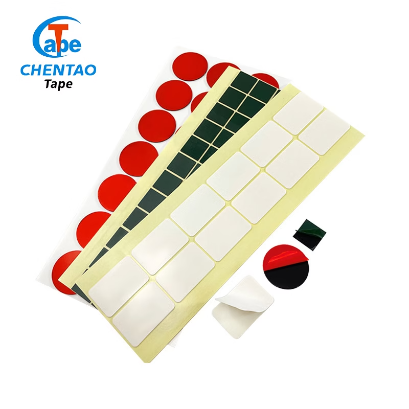
Die Cut Polyimide Tape: 5 Essential Applications
Die cut polyimide tape applications: ±0.1 mm tolerance, 260°C rated, RoHS compliant. PCB pad, EV cell, and motor slot liner custom shapes. Request samples.
On this page
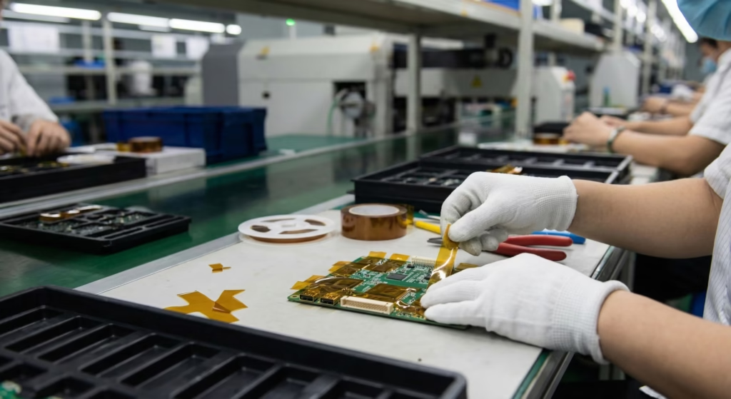
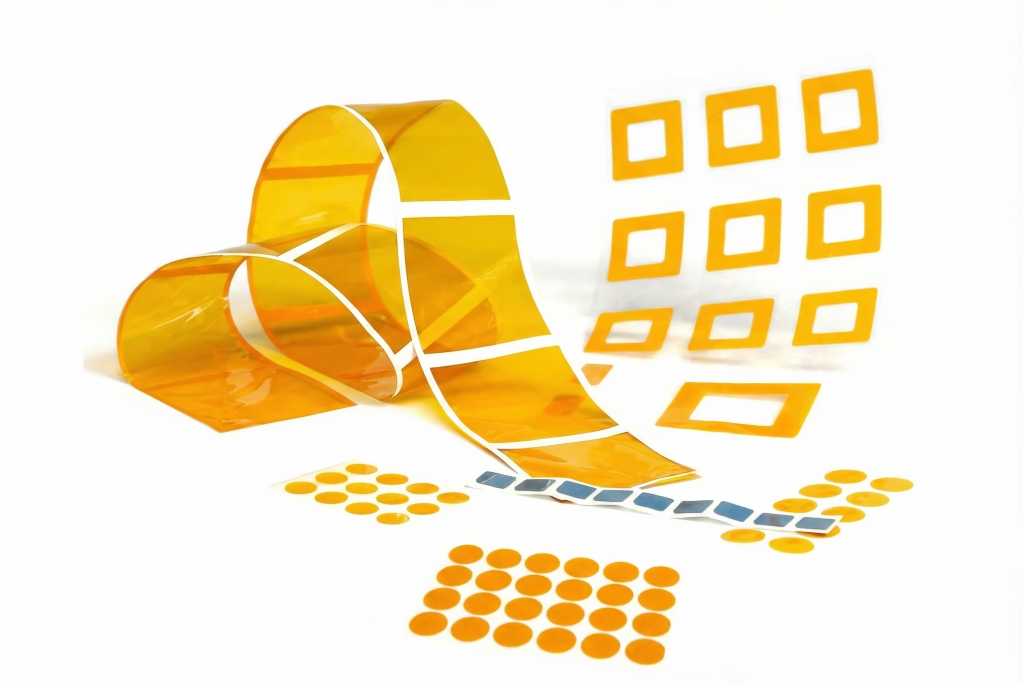
Die cut polyimide tape is polyimide film pre-converted from roll into precision shapes — circles, rectangles, slots, custom contours — that hold ±0.1 mm tolerances across PCB assembly, EV battery, motor winding, aerospace harness, and semiconductor processing. This article covers the five applications driving demand for die-cut over slit roll, the three conversion methods with their tolerance ceilings, and a specification checklist for first-time custom orders.
For the complete material science, adhesive selection, and grade overview, see the central reference: Polyimide Tape: Complete Engineering Guide (2026) — covering film properties, dielectric performance, IEC 60085 thermal class, and all major industry applications.
1. What Is Die Cut Polyimide Tape?
1.1 Roll Format vs Die-Cut Parts: Why Format Matters
Roll slit tape supplies continuous length that operators cut on-line, introducing waste from misaligned cuts and labor overhead per board. Die-cut discrete parts arrive pre-stamped on release liner, ready for pick-and-place or peel-and-stick without trimming.
The cost crossover appears at ~50,000 pieces/year, or whenever shape complexity makes hand-cutting impractical. Liner format options include individual parts on silicone liner sheet, parts on continuous pitch roll for semi-automated dispense, and parts in magazine tray for SMT feeders. “Custom die cut tape” applies to any shape ordered against a customer DXF or Gerber file; “die cut Kapton® tape” is a common sourcing phrase for the same category.
1.2 Polyimide Film Properties That Enable Precision Die Cutting
Aromatic polyimide film provides the mechanical platform for precision die cutting. High elastic modulus (2.5–3.5 GPa) limits elongation during stamping and produces sharp edge definition. Low CTE ~20 ppm/°C prevents dimensional drift between die-cutting and process temperature.
Film grades span 12.5 μm (fine-pitch masking) through 125 μm (heavy slot liner). DuPont’s Kapton® polyimide film established the 260°C service ceiling and dimensional stability benchmarks that IEC 60243 and ASTM D882 calibrate against; third-party PI film is verified against the same protocols. Silicone PSA leaves near-zero residue on gold and copper contacts after 260°C exposure — required for die-cut SMT masking. Acrylic PSA suits powder-coat oven masking and industrial shapes below 180°C.
2. Die-Cutting Methods and Precision Tolerances
2.1 Steel-Rule Die Cutting
Steel-rule blades bent to shape and set in a plywood board are pressed through the film stack, achieving ±0.1 mm on outer dimensions and ±0.15 mm on inner cutouts. The method handles sheet or roll-to-roll processing for simple shapes — circles, rectangles, slots — and suits run volumes from 5,000 pieces upward. Tool cost is low to moderate with 1–5 day setup; minimum inner radius is approximately film thickness × 3.
2.2 Laser Cutting
CO₂ or UV laser ablates film along a vector path without mechanical contact, achieving ±0.05 mm tolerance and complex inner geometries including micro-features below 0.3 mm radius. The edge is smooth and burr-free, with slight carbonization as PI film absorbs CO₂ laser energy. No tooling cost and hour-scale setup suit low-to-medium volume, high-mix programs: prototypes, aerospace lot-traceable short runs, and NPI iterations. Throughput per unit time is slower than steel-rule at high volume, setting the economic crossover for OEM programs.
2.3 Rotary Die Cutting
A hardened cylinder die mounted on a rotary press cuts continuously as film unwinds and re-winds at up to 150 m/min. Tolerance is ±0.05–0.10 mm with very high throughput, making rotary the preferred method for volumes exceeding 100,000 pieces per month on simple-to-moderate geometry parts, including SMT circuit masking shapes and EV pouch cell tabs.
2.4 Tolerance and Capability Summary
Scroll sideways to compare all columns.
| Method | Outer-dim tolerance | Inner-dim tolerance | Min inner radius | Best volume range |
|---|---|---|---|---|
| Steel-rule die | ±0.10 mm | ±0.15 mm | ~1.0 mm | 5,000–500,000 pcs |
| Laser cut | ±0.05 mm | ±0.05 mm | <0.3 mm | 10–50,000 pcs |
| Rotary die | ±0.05–0.10 mm | ±0.10 mm | ~0.5 mm | >100,000 pcs/month |
3. Application 1: PCB Pad and Connector Masking
Key Takeaway: Die-cut circles and edge-connector covers eliminate slit-tape overlap gaps that allow solder wicking at 260°C reflow — defect designed out, not inspected out.
3.1 Why Die-Cut Shapes Outperform Slit Tape for PCB Masking
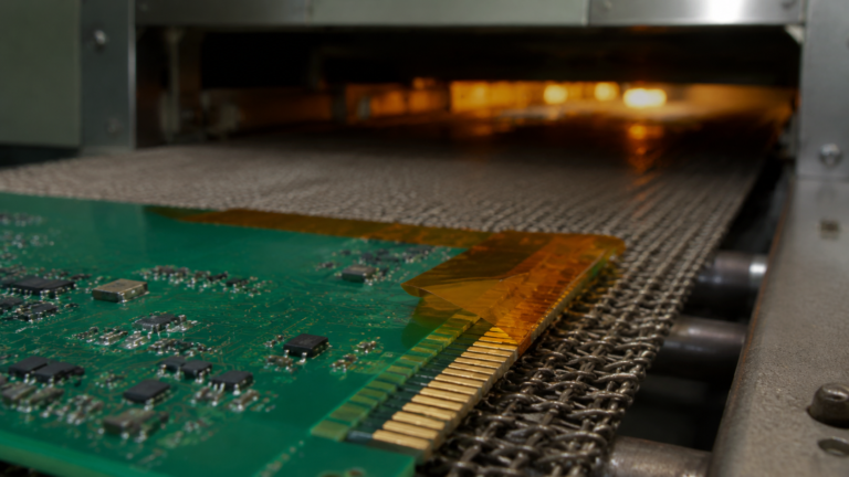
Wave solder and SMT reflow expose boards to 260°C bath or reflow peak profiles with 30–60 second dwell. Slit tape requires operators to mask each pad zone individually, producing inconsistent edge seals and overlap gaps that allow solder wicking under the tape edge. Die-cut circles for via and pad masking deliver consistent coverage in a single step. Die-cut edge connector covers provide full-length gold-finger coverage in one peel-and-place, replacing stacks of overlapping narrow slit strips.
Solder bridging from imprecise masking is a common NPI defect; a standardized die-cut part eliminates the dimensional variable. Automotive applications — IATF 16949 lot traceability — apply the same principle at higher volume with AQL-verified inspection.
3.2 Common Shape Library
Standard PCB shapes include circles Ø1.0–Ø30 mm for BGA land coverage, via plug masking, and through-hole fill. Rectangles cover edge connector zones at pitches 0.5/0.635/0.8/1.0 mm plus test point arrays. Slot and dog-bone shapes address press-fit connector zones; pocket arrays stamp multiple mask zones as one part for simultaneous robot placement. Custom contours convert from CAD within 3–5 business days after DXF or Gerber submission.
Specify 25 μm film for BGA/connector masking and 50 μm for through-hole plug. Silicone PSA is mandatory — acrylic residue on gold contacts causes solderability failure per IPC-A-610 Class 3. Sequential-pitch continuous roll format with 2 mm pitch tolerance is required for robot pick-and-place.
4. Application 2: EV Battery Cell Insulation
Key Takeaway: PI film’s 5,000–7,000 V dielectric per 25 μm and CTE match to aluminum cell cans (~20 vs ~23 ppm/°C) prevents wrinkles in 800 V bus architectures.
4.1 Thermal and Electrical Demands in Battery Packs
Lithium-ion pouch and prismatic cells operate −20°C to +60°C ambient with internal temperatures reaching 80–120°C during fast charge/discharge. Thermal runaway propagation can exceed 400°C locally. Inter-cell insulation prevents electrical shorts that trigger thermal cascade and provides a mechanical buffer during expansion cycling.
Dielectric requirements for 800 V DC bus packs specify ≥3 kV AC withstand per IEC 60243 at final insulation thickness. PI film outperforms PET and polypropylene: PI dielectric strength reaches 5,000–7,000 V per 25 μm versus PET at 3,000–4,500 V per 25 μm — a clear advantage at cell-level voltage differentials in modern BEV architectures.
4.2 Cell Wrapping, Tab Insulation, and Corner Protection
Die-cut format addresses three insulation geometries within a battery module. Cell body wrapping uses 25–50 μm PI film as a rectangular blanket, wrapped around the cell with the overlap seam sealed. Tab insulation — protecting terminals from inter-cell contact — uses U-channel or C-channel shapes that fold over the terminal ear. Corner protection shapes over pouch cell corners reduce mechanical stress during vibration cycling.
Prismatic modules also incorporate flat rectangular PI film interleaf between cells in module stacks; non-adhesive laminated film prevents cell-to-cell adhesion while maintaining registration during thermal expansion. Tight pitch-roll delivery formats match cell assembly line conveyor speeds.
4.3 Format and Material Selection for EV Cell Applications
Film thickness balances flexibility and structural stiffness: 25 μm for pouch cell wrapping, 50 μm for prismatic tab insulation where stiffness holds the shape in assembly fixtures. CTE ~20 ppm/°C matches aluminum cell cans at ~23 ppm/°C, eliminating wrinkle and buckle during thermal cycling versus PET film at CTE ~60 ppm/°C.
Nitto Denko’s EV battery film laminate products serve as volume benchmark in Japanese OEM qualification programs; independently produced PI die-cuts must demonstrate equivalent dielectric withstand and dimensional retention. Laser cutting is preferred for complex tab shapes (±0.05 mm at tab ear cutout); steel-rule suits high-volume rectangular blankets.
5. Application 3: Electric Motor Slot Liner Die-Cuts
Key Takeaway: Slot liner geometry is non-rectangular — width tolerance ±0.2 mm is critical; PI film is IEC 60454-3-7 Class H/C for traction motors.
5.1 Why Slot Liners Require Die-Cut Format
A motor slot liner is an insulation blank inserted into the stator slot before winding. The blank must conform precisely to slot cross-section geometry — trapezoidal or rounded-bottom profiles that vary by frame size. Slit roll tape cannot form a slot liner because geometry is non-rectangular and overhang must be controlled to ±0.2 mm for automated insertion without jamming.
IEC 60085 sets the material standard: Class H (180°C) or Class C (>220°C) for EV traction motors. PI film is a recognized Class H/C insulating component per IEC 60454-3-7. Width tolerance is critical — oversize blanks jam during insertion; undersize blanks leave insulation gaps at slot corners that reduce dielectric withstand below pack voltage.
5.2 Geometry Specification for Motor Slot Liners
Slot profile dimensions required for a die-cut order include slot width at the opening and bottom, slot depth, corner radius, and overhang length per side. Standard overhang is 3–8 mm per side; the overhang folds up after insertion to protect winding wire exit from slot edge burrs.
Film thickness: 50 μm for Class H EV motor slot liners (balancing mechanical durability with slot fill factor); 75 μm for Class C motors or high-power-density applications with peak transients to 240°C; 25 μm overlay as secondary reinforcement over sharp slot-opening edges.
5.3 Related Application: Aerospace Connector and Harness Parts
Aircraft engine bay environments expose harness components to 175–200°C continuous, peaks to 300°C short-term, plus vibration and hydraulic fluid. Avionics wiring must meet UL 94 V-0, FAR 25.853 low-smoke, and NASA STD 6001 Class A outgassing for spacecraft. AS9100D lot-traceable certificates from film through converter are mandatory. Connector boot overlays (MIL-DTL-38999, D-sub backshells), wrap-around patches, and slot liner geometries equivalent to EV motor applications all use the same PI tape formats, with MIL-W-22759 wire insulation class applying. Laser cutting is preferred for traceability — logged per batch, eliminating die-wear drift over long runs.
5.4 Extension: Semiconductor and Flat-Panel Display Processing
Wafer-level and advanced packaging use PI tape as temporary bonding during singulation, wafer thinning, and flip-chip pick-and-place, releasing cleanly with UV or thermal de-bond. FPD backplane fabrication uses PI film as substrate carrier during TFT array deposition, die-cut to ±0.05 mm achievable only with laser cutting. Low CTE PI prevents overlay misregistration during 150–250°C photolithography bake cycles (PET CTE is ~3× higher). Fab cleanliness requires particle count per part at ISO Class 3+; parts must be clean-room bagged at the point of cutting. ASTM E595 TML ≤1.0% and CVCM ≤0.1% outgassing limits apply to space applications — silicone PSA qualifies, acrylic does not.
6. Liner and Carrier Selection for Automated Dispensing
Key Takeaway: PET liner at 50–75 μm with EIA-481 sprocket holes (4 mm pitch) is required for SMT; glassine is fine for manual dispense.
6.1 Silicone Release Liner (Standard)
Glassine or PET base with silicone release coating is the standard liner for manual peel-and-apply and semi-automated dispense. Liner thickness runs 50–100 μm; 75 μm balances rigidity for easy peel against roll compactness. Release force of 5–20 cN/cm keeps thin 25 μm PI film from distorting during peel.
6.2 PET Liner for High-Speed SMT Automation
Clear 50–75 μm PET liner provides higher rigidity than glassine, maintaining part position under high-speed pick-and-place vacuum nozzle. Sequential pitch rolls space parts at 4/8/12 mm intervals matching EIA-481 SMT tape pocket pitch standards, with 4 mm sprocket holes for reel feeder engagement. A paper or clear PET cover tape peels back at the feeder for part pickup.
6.3 Pancake vs Traverse Winding
Pancake winding produces flat rolls for low-to-medium thickness parts that unwind without twist. Traverse (helical) winding distributes parts evenly across reel width to prevent edge crush on thick-liner rolls — preferred for 50–75 μm PI die-cut parts on long-length production reels.
7. Design-to-Order Specification Checklist
7.1 Geometry Parameters
Every inquiry requires: shape type (circle, rectangle, slot, or custom contour with DXF or Gerber); all critical dimensions with bilateral tolerances; inner cutout count and minimum radius; corner radius (sharp for laser, minimum 0.5 mm for steel-rule); and overall bounding box envelope, which determines die size and liner roll width.
7.2 Material Stack Definition
Specify film thickness (12.5/25/50/75/125 μm), adhesive type (silicone PSA for 260°C, acrylic PSA for ≤180°C, or non-adhesive laminate), liner type and thickness, cover tape requirement, and applicable temperature class with standard reference (IEC 60085 Class H or C, NASA STD 6001).
7.3 Packaging Format and Lead Times
Prototype and sample orders via laser cutting carry no tooling cost and ship within 3–7 business days. First production runs with steel-rule or rotary die tooling require 15–25 business days including sample inspection and first article approval. Repeat orders against existing tooling fulfill in 5–10 business days; reference the prior order number for tooling retrieval. SMT reel format per EIA-481 requires 7″ or 13″ reel diameter plus cover tape and part pitch in millimeters.
8. Manufacturing Standards and Supplier Evaluation
8.1 Material and Process Standards
Film used in die-cut polyimide tape applications is verified against IEC 60454-3-7, the polyimide electrical insulating film tape specification. Electrical performance is tested to ASTM D149 (dielectric breakdown), ASTM D257 (volume resistivity), and IEC 60243 (breakdown strength). Mechanical properties follow ASTM D882 (tensile strength and elongation) and ASTM D3330 (peel strength at 180°). Thermal class certification references IEC 60085 and IEC 60216 thermal endurance protocols, with UL 746B for high-temperature performance. Environmental compliance includes RoHS Directive 2015/863/EU, REACH SVHC below 0.1% w/w, and halogen-free status per IEC 61249-2-21.
9. Frequently Asked Questions
What tolerances can die cut polyimide tape achieve?
Steel-rule achieves ±0.1 mm on outer dimensions and ±0.15 mm on inner cutouts for PI film 12.5–75 μm. Laser achieves ±0.05 mm and inner radii below 0.3 mm. Rotary die is the tightest continuous process at ±0.05–0.10 mm for high-volume roll-to-roll. State your critical dimension tolerance in the inquiry so the converter selects the appropriate method.
Does the die-cutting process damage polyimide tape’s dielectric properties?
Steel-rule and rotary die cutting introduce no thermal stress; the cut edge retains the film’s original dielectric properties. Laser ablates a ~50 μm kerf and slightly increases surface energy, but does not change bulk dielectric strength or volume resistivity — IEC 60243 and ASTM D257 values apply across the full part. Verify with a sample report if your application is sensitive to cut-edge surface chemistry.
What is the minimum feature size achievable?
Steel-rule: minimum inner slot width ~1.0 mm, minimum outer dimension ~3.0 mm. Laser: minimum inner feature ~0.3 mm, minimum outer dimension ~0.5 mm. For micro-features below 0.5 mm, specify laser and provide a DXF with all feature radii explicitly dimensioned to avoid interpretation errors.
Can die cut polyimide tape parts be supplied on SMT pick-and-place reels?
Yes. Parts ship on EIA-481-compliant reel format: sequential-pitch on PET or glassine liner, covered with peel-back cover tape, wound on 7″ or 13″ plastic reels with 4 mm sprocket-hole pitch. Specify reel format, part pitch in millimeters, and reel diameter. First production lot should include a feeder compatibility test on your specific pick-and-place platform.
How is polyimide tape different from Kapton® tape in die-cut applications?
Kapton® is DuPont’s registered trademark for its polyimide film. The engineering specifications — IEC 60454-3-7, ASTM D882, ASTM D149 — define performance independent of brand. Third-party PI film die-cut to those specifications provides equivalent dimensional stability, dielectric withstand, and temperature performance. Specifying tolerance, film thickness, adhesive type, and test pass values rather than a brand trademark gives access to a broader converter base and shorter lead times.
How do I request samples or a custom die-cut quote?
Provide: shape geometry (DXF, Gerber, or dimensioned sketch with tolerances), film thickness, adhesive type (silicone or acrylic PSA), quantity, packaging format, and any applicable standard (IEC 60085 class, AS9100D traceability, RoHS). Catalog shapes (circles Ø3–Ø25 mm, standard rectangles) ship within 5 business days for fit-check. Custom tooled shapes require 15–25 business days for first production lot. To get a quote or download datasheets, visit the polyimide tape products page or contact us.
Related Engineering Guides
Scroll sideways to compare all columns.
| Article | Focus |
|---|---|
| Polyimide Tape: Complete Engineering Guide (2026) | Material science, adhesive systems, grades, full application taxonomy |
| Polyimide Tape Datasheet: Engineering Guide to Key Specs | Dielectric breakdown, tensile strength, peel force test tables |
| How to Use Polyimide Tape for Masking | PCB application technique, surface preparation, removal procedures |
| High-Temperature Polyimide Tape: 5 Ultimate Applications | Depth treatment of PCB reflow, EV motor, transformer applications |
Find the right tape for your application
Tell us what you need to bond, your operating conditions and the size or quantity you have in mind. Our team can help with material selection, samples and a quotation.
Discuss my application